Product Description
Product Description:
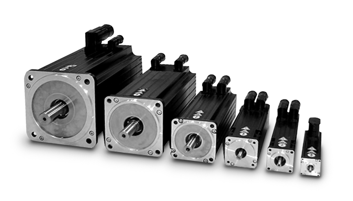
DC motor is a rotating motor that can convert DC electric energy into mechanical energy (DC motor) or mechanical energy into DC electric energy (DC generator). It is a motor that can convert DC and mechanical energy into 1 another. When it runs as a motor, it is a direct current motor, which converts electrical energy into mechanical energy; when it runs as a generator, it is a direct current generator, which converts mechanical energy into electrical energy.
| Product Name | Industrial Sewing Machine Servo 220V DC Motor |
| Motor Type | DC Motor,ACMotor,Stepper Motor,Asynchronous Motor ,Synchronous Motor (Electric machinery) |
| Composition structure | The structure of DC motor should consist of 2 parts: stator and rotor. The static part of DC motor is called stator. The main function of stator is to generate magnetic field, which is composed of base, main magnetic pole, commutation pole, end cap, bearing and brush device. Running part is called rotor, whose main function is to generate electromagnetic torque and inductive electromotive force. It is the hub of energy conversion of DC motor. So it is also commonly called armature, which consists of rotor, armature core, armature winding, commutator and fan. |
| Model | Z Type |
| Seat number | Z315-Z1000 |
| power | 60~2800kW |
| Voltage | 220~1000V |
| Torque range | 1.5 ~180kNm |
| Protection level | IP23, IP44 |
| Cooling mode | IC06,IC17,IC37,IC81W |
| Operating speed | Constant Speed /Low Speed /Adjust Speed /High Speed Other |
| Main classification | DC Motor is a machine that converts mechanical energy into DC power. It is mainly used as DC motor for DC motor, electrolysis, electroplating, smelting, charging and excitation power supply of alternator. Although in places where DC power is needed, AC power rectifier is also used to convert AC into DC power, but from some aspects of performance, AC rectifier power supply can not completely replace DC generator. |
| Application | DC motors are widely used in tape recorders, video recorders, video discs, electric shavers, hair dryers, electronic watches, toys and so on. |
| Maintenance method | Professional motor maintenance center motor maintenance process: cleaning stator and rotor – replacing carbon brush or other parts – vacuum F pressure dipping paint – drying – Calibration balance. 1. Use environment should be always dry, motor surface should be kept clean, air intake should not be hindered by dust, fibers and other obstacles. 2. When the thermal protection of the motor continues to operate, it should be ascertained whether the fault comes from the motor or the overload or the setting value of the protective device is too low. After eliminating the fault, it can be put into operation. 3, ensure that the motor is well lubricated during operation. The general motor runs for about 5000 hours, that is to say, lubricating grease should be added or replaced. When bearing overheating or lubricating deterioration is found in operation, the hydraulic pressure should change lubricating grease in time. When replacing grease, the old grease should be removed, and the oil groove of bearing and bearing cover should be washed with gasoline. Then ZL-3 lithium grease should be filled with 1/2 (2 poles) and 2/3 (4 poles, 6 poles and 8 poles) of the cavity between the inner and outer rings of the bearing. 4. When the life of the bearing is over, the vibration and noise of the motor will increase obviously. When the radial clearance of the bearing reaches the following value, the bearing should be replaced. 5, when removing the motor, it is OK to remove the rotor from the shaft extension or the non extension end. If it is not necessary to unload the fan, it is more convenient to take out the rotor from the non-axle extension end. When pulling out the rotor from the stator, the stator winding or insulation should be prevented from being damaged. 6. When replacing the windings, the form, size, turns and gauges of the original windings must be recorded. When these data are lost, they should be obtained from the manufacturer and the original designed windings should be changed at will, which often deteriorates 1 or several performance of the motor or even makes it impossible to use them. |
/* January 22, 2571 19:08:37 */!function(){function s(e,r){var a,o={};try{e&&e.split(“,”).forEach(function(e,t){e&&(a=e.match(/(.*?):(.*)$/))&&1
| Application: | Universal, Industrial, Household Appliances, Car, Power Tools |
|---|---|
| Operating Speed: | High Speed |
| Excitation Mode: | Compound |
| Function: | Control, Driving |
| Casing Protection: | Closed Type |
| Number of Poles: | 8 |
| Customization: |
Available
|
|
|---|

How are servo motors used in CNC machines and other precision machining equipment?
Servo motors play a crucial role in CNC (Computer Numerical Control) machines and other precision machining equipment. They provide precise and dynamic control over the movement of various axes, enabling high-accuracy positioning, rapid speed changes, and smooth motion profiles. Here’s a detailed explanation of how servo motors are used in CNC machines and precision machining equipment:
1. Axis Control:
CNC machines typically have multiple axes, such as X, Y, and Z for linear movements, as well as rotary axes for rotational movements. Servo motors are employed to drive each axis, converting electrical signals from the CNC controller into mechanical motion. The position, velocity, and acceleration of the servo motors are precisely controlled to achieve accurate and repeatable positioning of the machine’s tool or workpiece.
2. Feedback and Closed-Loop Control:
Servo motors in CNC machines are equipped with feedback devices, such as encoders or resolvers, to provide real-time information about the motor’s actual position. This feedback is used in a closed-loop control system, where the CNC controller continuously compares the desired position with the actual position and adjusts the motor’s control signals accordingly. This closed-loop control ensures accurate positioning and compensates for any errors, such as mechanical backlash or load variations.
3. Rapid and Precise Speed Changes:
Servo motors offer excellent dynamic response, allowing CNC machines to achieve rapid and precise speed changes during machining operations. By adjusting the control signals to the servo motors, the CNC controller can smoothly accelerate or decelerate the machine’s axes, resulting in efficient machining processes and reduced cycle times.
4. Contouring and Path Tracing:
CNC machines often perform complex machining tasks, such as contouring or following intricate paths. Servo motors enable precise path tracing by accurately controlling the position and velocity of the machine’s tool along the programmed path. This capability is crucial for producing intricate shapes, smooth curves, and intricate details with high precision.
5. Spindle Control:
In addition to axis control, servo motors are also used to control the spindle in CNC machines. The spindle motor, typically a servo motor, rotates the cutting tool or workpiece at the desired speed. Servo control ensures precise speed and torque control, allowing for optimal cutting conditions and surface finish quality.
6. Tool Changers and Automatic Tool Compensation:
CNC machines often feature automatic tool changers to switch between different cutting tools during machining operations. Servo motors are utilized to precisely position the tool changer mechanism, enabling quick and accurate tool changes. Additionally, servo motors can be used for automatic tool compensation, adjusting the tool’s position or orientation to compensate for wear, tool length variations, or tool offsets.
7. Synchronized Motion and Multi-Axis Coordination:
Servo motors enable synchronized motion and coordination between multiple axes in CNC machines. By precisely controlling the servo motors on different axes, complex machining operations involving simultaneous movements can be achieved. This capability is vital for tasks such as 3D contouring, thread cutting, and multi-axis machining.
In summary, servo motors are integral components of CNC machines and precision machining equipment. They provide accurate and dynamic control over the machine’s axes, enabling high-precision positioning, rapid speed changes, contouring, spindle control, tool changers, and multi-axis coordination. The combination of servo motor technology and CNC control systems allows for precise, efficient, and versatile machining operations in various industries.
What factors should be considered when selecting a servo motor for a specific application?
When selecting a servo motor for a specific application, several factors need to be considered. These factors help ensure that the chosen servo motor meets the requirements and performs optimally in the intended application. Here are some key factors to consider:
1. Torque and Power Requirements:
One of the primary considerations is the torque and power requirements of the application. The servo motor should be able to generate sufficient torque to handle the load and overcome any resistance or friction in the system. Additionally, the power rating of the motor should match the power supply available in the application. It is essential to evaluate the torque-speed characteristics of the servo motor to ensure it can deliver the required performance.
2. Speed and Acceleration:
The required speed and acceleration capabilities of the servo motor should align with the application’s needs. Different applications have varying speed and acceleration requirements, and the servo motor should be able to meet these demands. It is crucial to consider both the maximum speed that the motor can achieve and the time it takes to accelerate or decelerate to specific speeds. Evaluating the servo motor’s speed-torque characteristics and acceleration capabilities is necessary for selecting the right motor.
3. Positioning Accuracy and Repeatability:
The desired positioning accuracy and repeatability of the application play a significant role in servo motor selection. If precise positioning is crucial, a servo motor with high accuracy and low positioning errors should be chosen. The feedback mechanism, such as encoders or resolvers, should provide the required resolution to achieve the desired accuracy. Repeatability, the ability to consistently reach the same position, should also be considered, especially in applications where repetitive movements are necessary.
4. Environmental Conditions:
The environmental conditions in which the servo motor will operate should be taken into account. Factors such as temperature extremes, humidity, dust, and vibration can affect the motor’s performance and lifespan. In harsh environments, it may be necessary to choose a servo motor with appropriate protection ratings, such as IP (Ingress Protection) ratings, to ensure reliable operation and longevity.
5. Control System Compatibility:
The compatibility of the servo motor with the control system used in the application is crucial. The motor should be compatible with the control signals and communication protocols employed in the system. This includes considerations such as voltage compatibility, control signal types (analog, digital, pulse), and communication interfaces (such as Ethernet, CAN, or Modbus). Ensuring compatibility will facilitate seamless integration and efficient control of the servo motor within the application.
6. Size and Weight Constraints:
The physical size and weight limitations of the application should be considered when selecting a servo motor. The motor’s dimensions should fit within the available space, and its weight should not exceed the application’s weight capacity. Compact and lightweight servo motors may be preferred in applications where space is limited or weight is a critical factor.
7. Cost Considerations:
The cost of the servo motor and its overall value for the application should be evaluated. It is essential to consider the initial purchase cost as well as the long-term maintenance and operational costs. While cost is a factor, it should not be the sole determining factor, as compromising on quality or performance may lead to suboptimal results.
By considering these factors, one can make an informed decision when selecting a servo motor for a specific application. It is recommended to consult with manufacturers or experts in the field to ensure the chosen servo motor meets the application’s requirements and provides reliable and efficient performance.

How does feedback control work in a servo motor system?
In a servo motor system, feedback control plays a crucial role in achieving precise control over the motor’s position, speed, and acceleration. The feedback control loop consists of several components that work together to continuously monitor and adjust the motor’s behavior based on the desired and actual position information. Here’s an overview of how feedback control works in a servo motor system:
1. Position Reference:
The servo motor system starts with a position reference or a desired position. This can be specified by a user or a control system, depending on the application requirements. The position reference represents the target position that the servo motor needs to reach and maintain.
2. Feedback Sensor:
A feedback sensor, such as an encoder or resolver, is attached to the servo motor’s shaft. The purpose of the feedback sensor is to continuously measure the motor’s actual position and provide feedback to the control system. The sensor generates signals that indicate the motor’s current position, allowing the control system to compare it with the desired position.
3. Control System:
The control system receives the position reference and the feedback signals from the sensor. It processes this information to determine the motor’s current position error, which is the difference between the desired position and the actual position. The control system calculates the required adjustments to minimize this position error and bring the motor closer to the desired position.
4. Controller:
The controller is a key component of the feedback control loop. It receives the position error from the control system and generates control signals that govern the motor’s behavior. The controller adjusts the motor’s inputs, such as voltage or current, based on the position error and control algorithm. The control algorithm can be implemented using various techniques, such as proportional-integral-derivative (PID) control, which adjusts the motor’s inputs based on the current error, the integral of past errors, and the rate of change of errors.
5. Motor Drive:
The control signals generated by the controller are sent to the motor drive unit, which amplifies and converts these signals into appropriate voltage or current levels. The motor drive unit provides the necessary power and control signals to the servo motor to initiate the desired motion. The drive unit adjusts the motor’s inputs based on the control signals to achieve the desired position, speed, and acceleration specified by the control system.
6. Motor Response:
As the motor receives the adjusted inputs from the motor drive, it starts to rotate and move towards the desired position. The motor’s response is continually monitored by the feedback sensor, which measures the actual position in real-time.
7. Feedback Comparison:
The feedback sensor compares the actual position with the desired position. If there is any deviation, the sensor generates feedback signals reflecting the discrepancy between the desired and actual positions. These signals are fed back to the control system, allowing it to recalculate the position error and generate updated control signals to further adjust the motor’s behavior.
This feedback loop continues to operate in a continuous cycle, with the control system adjusting the motor’s inputs based on the feedback information. As a result, the servo motor can accurately track and maintain the desired position, compensating for any disturbances or variations that may occur during operation.
In summary, feedback control in a servo motor system involves continuously comparing the desired position with the actual position using a feedback sensor. The control system processes this position error and generates control signals, which are converted and amplified by the motor drive unit to drive the motor. The motor’s response is monitored by the feedback sensor, and any discrepancies are fed back to the control system, enabling it to make further adjustments. This closed-loop control mechanism ensures precise positioning and accurate control of the servo motor.


editor by CX 2024-05-15